


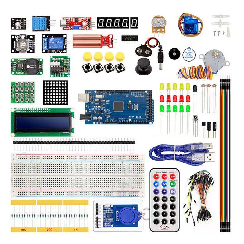
Smart Electronics 3D Printer Parts DIY Motherboard Kit Mega2560 + LCD Circuit Control Board

Smart Electronics 3D Printer Parts DIY Motherboard Kit Mega2560 + LCD Circuit Control Board
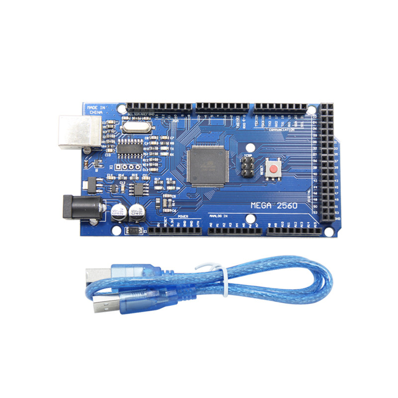
The diode D1 supplied by the ramps to the mega board is not welded, that is to say, the mega2560
board needs to be separately powered by usb5v or through the power connector (it is not recommended
to power more than 12V officially). Please understand. If you want to use LCD offline printing, you need to
power the ramps 1.4 yourself, otherwise you can't use it.

Special description
board needs to be separately powered by usb5v or through the power connector (it is not recommended
to power more than 12V officially). Please understand. If you want to use LCD offline printing, you need to
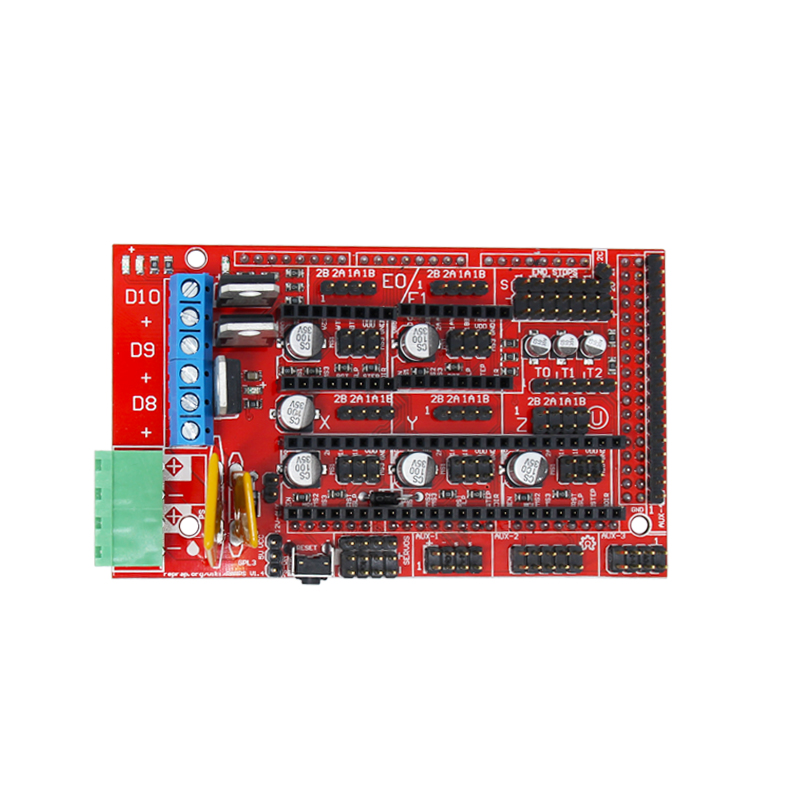
power the ramps 1.4 yourself, otherwise you can't use it. 2. If the power supply is connected reversely and the motor drive board is connected reversely, it may
burn the chip and circuit. Please confirm again and then power on.
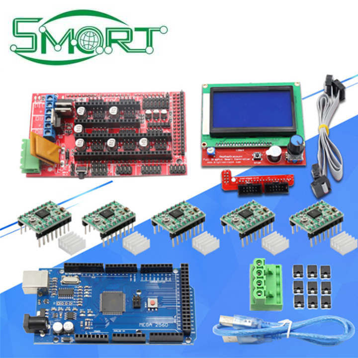
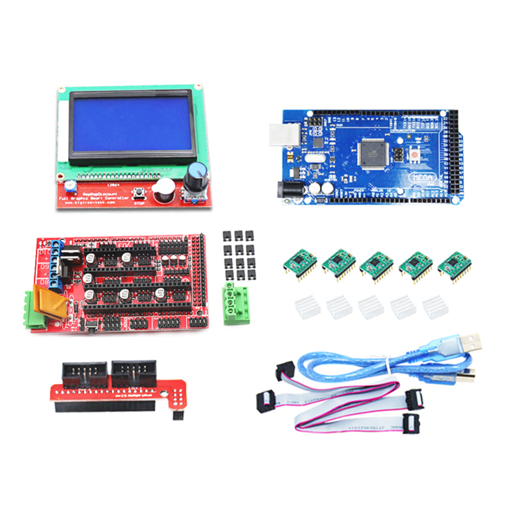
Modules and devices needed
the whole printer to complete specific actions, such as printing specific documents, etc
connect and control with other hardware and play a role of transition bridge
control of the main control board to the stepper motor, and realize the action of XYZ and extruder
and the motor is connected to ramps1.4 board
Generally, the heating head has two electrical elements, which can be used for heating after being electrified.
It is similar to the electric furnace thermistor to obtain the current temperature on the heating head, so as to achieve
better temperature control. Many operations are allowed only after the firmware obtains the temperature successfully,
So even if you do a simple test, you have to connect two thermistors (the other is used to get the temperature of the hot bed)
to the platform, the general solution is to use a hot bed, which also includes two parts, the heating part and the
thermistor, in which the thermistor is necessary;
yourself with a 2v100w ~ 200W power supply.
part cannot be tested. Other non essential parts mainly include 12V fan and at least three limit switches (if they are
not available, they will not affect the test of the circuit board, but will affect the use of the printer. If you do a
complete set of printers, this is necessary, especially the limit switch).
Burning fasteners
configuration. H file through tab and find "ifndef motherboard" #Define motherboard a number #endif Modified to #ifndef MOTHERBOARD #define MOTHERBOARD 33 #endif
Modify these parameters temporarily. Then select the menu tools board mega2560, and select tools serial port corresponding
serial port (generally the first from the bottom, it is not allowed to try other ports for several times). Click the right arrow icon
on the IDE to upload the firmware. If the installation is carried out according to the above steps, there should be no error.
And you can see another LED light on the main control panel will flash continuously, which means that it is being uploaded;
wait for the completion.


| SHENZHEN SMART ELECTRONICS CO.,LTD. |
|
|


